Technics SL- Replacing Signal and Ground Wire Manual how to
Submitted by LeadThis content is © 2007-2025 The DJResource
Opening the SL turntable
This DJ Topic describes how the Signal Wire of a Technics SL1200/ 1210 can be replaced.
Opening the top should is not required as the Signal Wire is directly connected to the wires that lead to the cartridge.
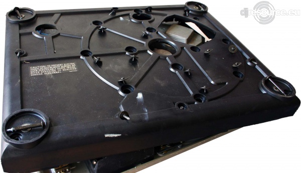
Before you can access the Arm Assy you need to open the SL's bottom side.
How to do this : Opening Technics SL1200/ 1210
Tools needed
Soldering WeldWire-cutter
Small knife
Philips Screwdriver small
Flat Screwdriver small
Part List
Prefab cable : RCA to RCA, 1.5m
Ground wire : 1mm2, 1.5m
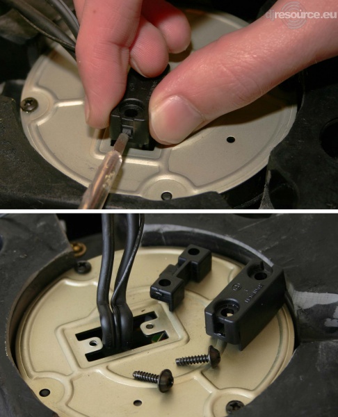
Remove the Cord Clamp
First remove the screws of the Cord Clamper with a Philips type screwdriver. The Clamper is attached to the spacer with two claws
After removing the screws the Clamper is still held in it's place by 2 small clips. Use a small flat screwdriver to release them.
When this is done you can lift the Clamper off, the Spacer can now also be removed.
Remove the Back Plate
Now unscrew the two tiny screws that hold the metal Cover Plate. Keep all screws on a safe place (like an empty cup or dish) so you don't loose any.
Lift the Cover Plate out of it's place, use your other hand to guide the signal wire through the hole. Be careful as the edge of the Cover Plate can cut into the wire.
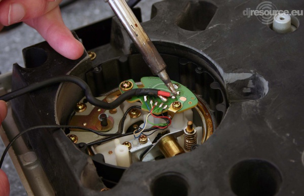
Remove the old wires
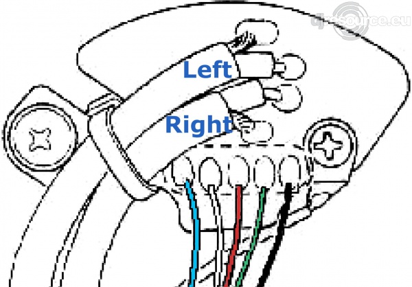
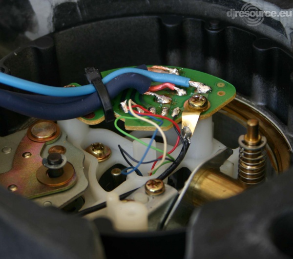
After the Cover is removed you'll see a circuit board to which the Signal wires are soldered. As an extra safety there should be a Cable-t that holds the wire to the circuit board.
Cut the Cable-t and de-solder the Signal wires. The red wired is the right signal and the white wire carries the left signal or a standard cable.
Start with de-soldering the ground wires and then the signal wire. After de soldering all the wires you need to remove the most of the solder on the contacts of the circuit board.
Also cut the ground wire as close to the beginning as possible.
Stereo Signal
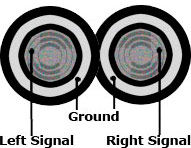
To transport a stereo signal a total of 4 wires is needed. Each channel (Left and Right) need 2 wires: A signal wire and a ground wire.
Usually the ground signal is wrapped around the signal wire inside the cable so it forms a ground-shield to protect the signal from external distortions.
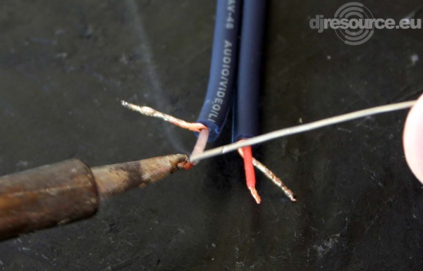
Prepare the Signal Wires
After cutting a set of Signal Cables to the desired length (probably 1,5 meters) you'll need to strip the ends (about 1-1.5cm). Be careful us you need to make a cut with a sharp knife in the outer shell of the cable without damaging the copper wires. This goes best when you hold the cable bend 180 degrees while cutting.
After stripping you must twist ALL copper wires. Strip 3mm from the signal wire that is in the center of all copper wires and also twist this end. Apply tin at the ends of all twisted wires. Apply just the right amount of tin: drain all wires but don't let drops appear.
When the Signal Cables of a SL12xx are replaced it's advised that you also replace the ground wire as it is probably in the same state as the signal wires.
Prepare the Ground Wire
The best replacement Ground Wire has a copper core and a diameter of about 0.75 or 1mm. This is a lot thicker than the standard wire so it should keep up for a lot longer. Cut the ground wire at the same length as the signal wires and strip about 1cm at one end and 5mm at the other end.
At the 5mm end to need to apply some tin with the solder weld so all copper is drained with tin. This end will be mounted to the circuit board.
The other 10mm end will be used to connect to your turntable. Some prefer the open end, but there is a downside to it. When you use the open end and you need to connect the turntable to a lot of different mixer, you'll notice that the ground wire will get shorter and shorter because each time a few copper wires will break off... and at the end you'll need to strip it again.
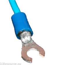
I would go for a better solution : mounting a connector to the end. I used a small round one and cut a gap in it so you can slide it over the ground screw thread of the mixer.
Fold 5mm of the 10mm end so you get a short thick end and twist this as good as you can. Get this end into the connector so that you cannot see any copper where the wire is inserted into the connector.
Now heat the connector from the from with the solder welt and apply a decent amount of tin on it. Make sure the wire is soaked with tin so the connection of held firmly on its place. Check this by trying to pull the wire out of the connector, it can better break now than at a later moment 
Mounting the Signal Wires
Once the Signal Wire is pre-soldered, making the final connection should be very simple: hold the wire to it's place, heat it with the solder welt and add the tin at the point where they touch.
First solder the signal wires, then shorten the ground wire to the desired length and finally also weld the ground wires.
In case any of the tiny wires got lose or when you need to replace the complete Arm Assy, you might like this scheme diagram that gives a clear overview from the actual connections.
Mounting the Ground Wire
Actually there are 2 solutions to handle the ground wire. The preferred way is the original way. The original Ground Wire was connected to that lip on the right, just next to the other black wire before I cut it. That is where is supposed to be mounted, but it's rather close to the tiny wires that go into the arm.
On the circuit board however there is a mounting place dedicated for a ground wire as you can see in this picture. It perfectly aligns the cable with the Signal Wires.
Make sure to tighten a new Cable-t so that the new signal wire is held at it's place at all times.
Assembling
Now all work is done all has to be assembled again. This goes in the opposite order
- Mount the Cover Plate with the 2 smallest screws.
Feed the Cinch connectors through the hole one by one, avoid cuts by the Cover plate in the Signal and Ground wires. - Mount the Cord Spacer first
- Fold the wires over it
- Mount the Cord Clamper and screw it firmly at it's place
- Re assemble the base.
If you forgotten the location of some screws, check the image (enlarge it) that is in this topic.
What do you think about Technics SL- Replacing Signal and Ground Wire ??
Please consider making this website possible by disabling your Ad Blocker.
Or become a Gold Member, they don't see ads.
There are 5 Comments
goed werk Lead, en wat is het volgende?
Hebben jullie dat betere foto's van?
Wel mooi uitgelegd allemaal, op zich ook allemaal niet zo moeilijk he


Deze handleiding heeft me zeer goed geholpen!!
Some parts of this website require you to login. Using an account on DJResource has a lot of advantages such as:
Adding Content, getting Notifications, Like content, Downloading and Uploading Images and much more.
Create your account to get involved with the Community
Most visitors online this month : 78
Lifetime Pageviews since 2003 : 239.376.861

